
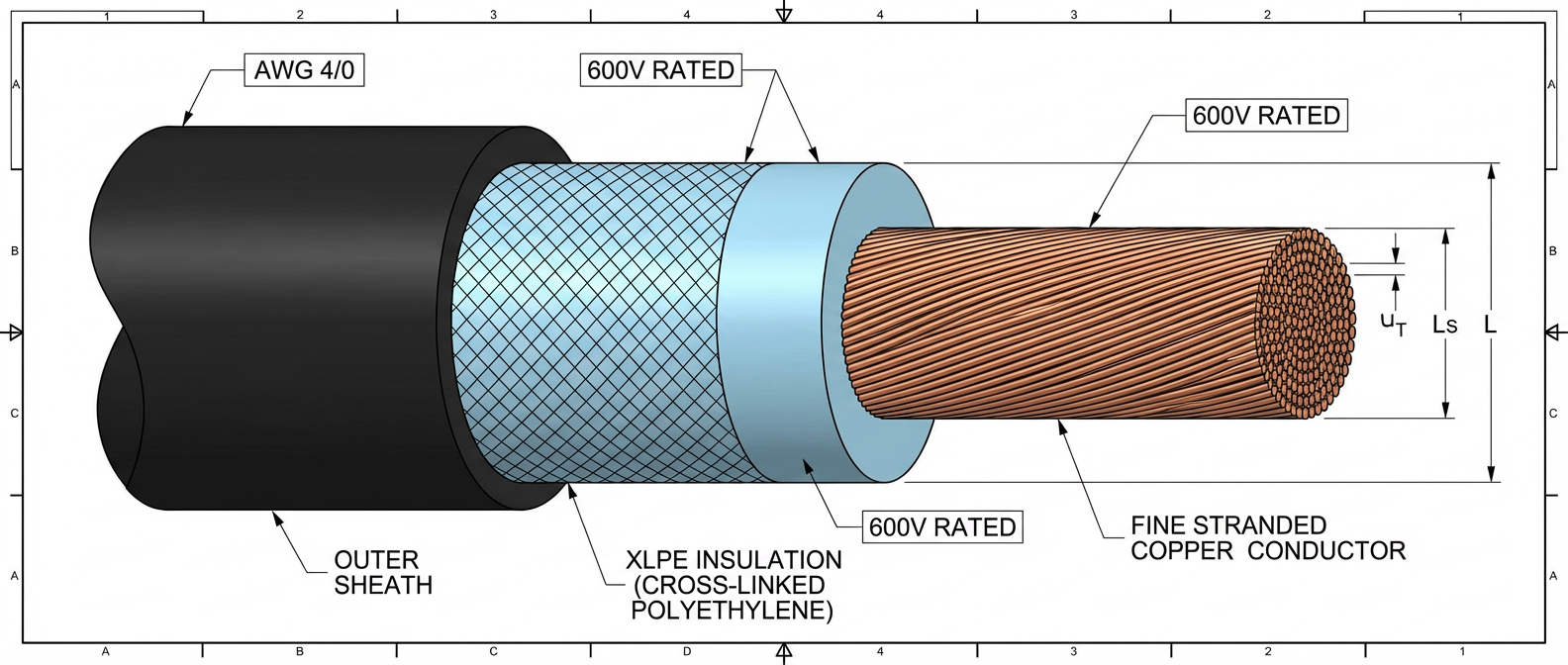
The selection of battery cables is a foundational aspect of designing safe, reliable, and efficient electrical systems, particularly in demanding applications like automotive, marine, renewable energy storage, and industrial equipment. An incorrect choice can lead to voltage drop, overheating, energy loss, catastrophic failure, or safety hazards. This comprehensive guide synthesizes key engineering findings to inform the cable selection process, focusing on six critical pillars: conductor, insulation, termination, safety, installation, and standards.
1. Conductor Selection: Material, Gauge, and Stranding
The conductor is the core of the cable, responsible for carrying current. Its material and construction are paramount.
- Material: Copper is the dominant choice due to its superior conductivity (approximately 1.7 x 10⁻⁸ Ω·m), excellent flexibility, and resistance to corrosion. While aluminum offers a lighter and cheaper alternative, its higher resistivity (about 2.8 x 10⁻⁸ Ω·m) requires a larger cross-sectional area for equivalent current capacity, and it is more susceptible to creep and oxidation, which can increase resistance at connections over time. For most critical battery applications where reliability and minimized voltage drop are essential, high-purity, oxygen-free copper is recommended.
- American Wire Gauge (AWG): Proper gauge sizing is non-negotiable. The cable must be sized to handle the system’s maximum continuous current with minimal voltage drop (typically targeted below 3% for battery circuits). Undersized cables are the primary cause of overheating, insulation meltdown, and fire. Selection charts based on ampacity and length are essential tools. For high-current applications (e.g., starter motors, inverters), gauges between 4/0 AWG (0000) and 2 AWG are common. The longer the cable run, the larger the gauge required to combat resistance-induced voltage drop.
- Stranding: Fine-stranding (using many small wires) is vastly superior to a solid core for battery cables. It provides exceptional flexibility, crucial for routing in tight engine compartments or mobile installations, and significantly improves resistance to metal fatigue from vibration. The more strands, the more flexible and durable the cable.
2. Insulation and Jacket: The Protective Barrier
The insulation material defines the cable’s environmental resilience and durability.
- Material Properties: Common materials include PVC, Cross-Linked Polyethylene (XLPE), and Thermoplastic Elastomers (TPE like TPR).
- PVC is cost-effective and offers good general resistance but can become brittle in extreme cold and may soften or degrade under high under-hood temperatures.
- XLPE provides superior characteristics: excellent thermal stability (typically rated from -55°C to +125°C or higher), higher resistance to abrasion, fuels, oils, and acids. It is often the preferred choice for demanding environments.
- TPE/TPR compounds offer excellent flexibility across a wide temperature range and good chemical resistance.
- Key Ratings: Look for ratings for temperature (both high and low), oil resistance (SAE J1128 standards), flame retardancy, and sunlight/UV resistance (for marine or solar applications). The jacket should also be thick enough to provide robust mechanical protection against abrasion and crushing.
3. Termination and Connections: The Critical Interface
A perfect cable is only as good as its connection. Poor terminations are a leading point of failure.
- Terminal Type: Lugs must match the cable gauge precisely and be constructed from the correct material (e.g., tinned copper for corrosion resistance, especially in marine settings). They must also match the stud/bolt size of the battery post or busbar.
- Crimping vs. Soldering: A high-quality, heavy-duty crimp with a proper hexagonal or indent crimping tool is the industry standard for high-current applications. It creates a cold-weld, gas-tight connection that is highly resistant to vibration and corrosion. Soldering alone is generally discouraged for high-vibration environments as it can create a brittle joint at the solder-wire interface, leading to fatigue failure. A hybrid approach (crimp then light solder fill) is sometimes used but requires expert execution.
- Corrosion Prevention: The use of heat-shrink tubing with an internal sealant (adhesive-lined) over the crimp is a best practice. This seals out moisture, oxygen, and corrosive agents, dramatically extending connection life. Applying a thin layer of anti-oxidant compound on aluminum conductors or in highly corrosive environments is also advised.
4. Safety and Performance Considerations
- Voltage Drop: This is the single most important performance metric after ampacity. Excessive voltage drop reduces efficiency, causes poor equipment performance (e.g., dim lights, slow cranking), and can lead to overheating as equipment draws more current to compensate. Calculations must consider total circuit length (round-trip for DC systems) and the cable’s resistance per foot at the operating temperature.
- Short-Circuit Protection: Battery cables must be protected by a fuse or circuit breaker as close to the battery positive terminal as possible. The protection device must be sized to protect the cable itself—it should blow before the cable overheats and causes a fire in the event of a short circuit. The inrush current of devices like starter motors must be considered when selecting fuse type (e.g., slow-blow).
- Routing and Protection: Cables must be securely supported with clamps to prevent movement and abrasion. They should be routed away from sharp edges, hot surfaces (exhaust manifolds), and moving parts. Conduit or protective loom should be used where abrasion is a risk.
5. Installation Best Practices
Proper installation ensures long-term reliability.
- Cleanliness: All connection points (battery terminals, lugs) must be clean and free of oxidation before assembly.
- Torque: Battery terminals and lug bolts must be tightened to the manufacturer’s specified torque. Under-tightening leads to high-resistance hot spots; over-tightening can damage terminals or studs.
- Strain Relief: Ensure cables are not under mechanical tension at the connection point, which can stress the termination.
6. Standards and Certifications
Adherence to recognized standards is a proxy for quality and safety assurance. Key standards include:
- SAE J1128: Standard for Low Voltage Primary Cable, defining construction, performance, and test requirements for automotive-type battery cables.
- UL / cUL Listed: Indicates the cable has been tested by Underwriters Laboratories for safety (fire, electrical) to applicable standards.
- ABS (American Bureau of Shipping) Type 1 or 2: Certification for marine cables, indicating suitability for shipboard use with specific flame retardancy and toxicity requirements.
Conclusion and Remaining Uncertainties
Selecting the correct battery cable is a systematic process that balances electrical requirements (current, voltage drop), mechanical demands (flexibility, vibration), environmental challenges (temperature, chemicals), and safety imperatives (short-circuit protection, fire resistance). The consensus prioritizes finely-stranded, high-purity copper conductors sized generously for the application, insulated with high-temperature, chemically-resistant material like XLPE, and terminated with professional-grade, sealed crimps.
Remaining uncertainties or context-dependent decisions include:
- Cost-Benefit Analysis for Niche Materials: For ultra-high-performance or weight-critical applications (e.g., aerospace, high-end racing), the cost-benefit analysis of advanced materials like silver-plated copper or specialized alloys requires more application-specific data.
- Long-Term Behavior of New Insulation Polymers: The long-term (10+ year) aging characteristics of newer polymer blends in real-world, combined-stress environments (thermal cycling + chemical exposure + UV) are an area of ongoing study.
- Optimal Fusing Strategies for Complex Systems: In advanced DC systems with lithium batteries, capacitors, and multiple distribution points, determining the ideal coordination of fuses and breakers to ensure selective tripping (isolating only the faulted branch) remains a nuanced engineering challenge. Simplified guidelines may not cover all complex architectures.
Ultimately, a conservative approach—oversizing slightly, using high-quality components, and following meticulous installation practices—is the most reliable strategy to ensure a battery cable system delivers safe, efficient, and trouble-free performance over its entire lifespan.




Add comment