

Introduction
DC coupling in Power Conversion Systems (PCS) is a critical technology for enhancing efficiency and flexibility in modern energy systems, particularly in renewable energy applications like solar photovoltaic (PV) and battery energy storage systems (BESS). Unlike AC coupling, which involves converting DC sources to AC before integration, DC coupling directly connects multiple DC sources (e.g., PV arrays and batteries) to a common DC bus, minimizing conversion losses and simplifying system architecture. This approach is gaining traction due to its potential for higher energy yields and cost savings in grid-tied or off-grid installations. However, it introduces technical complexities that require careful design and management. This summary synthesizes key insights into what DC coupling is, its implementation, technical challenges, difficulties, and practical considerations, drawing from industry standards, academic research, and real-world applications. Despite advancements, uncertainties remain regarding scalability, emerging technologies, and evolving regulations. (Sources: IEEE Transactions on Power Electronics, IEC standards, and manufacturer white papers such as those from SMA Solar Technology and Tesla.)
1. What is DC Coupling?
DC coupling refers to the direct electrical connection of DC power sources to a shared DC bus within a PCS, without intermediate AC conversion stages. In this configuration, sources like PV panels or batteries feed into a common DC voltage level, which is then converted to AC by a single inverter for grid or load use. This contrasts with AC coupling, where each source has its own inverter, leading to potential inefficiencies. The core advantage of DC coupling is reduced energy loss; for instance, PV-generated DC can directly charge batteries or supply loads, avoiding the 5-10% conversion losses typical in AC-coupled systems. This makes it ideal for hybrid systems where multiple DC sources need seamless integration, such as in residential solar-plus-storage setups. According to the National Renewable Energy Laboratory (NREL), DC coupling can improve overall system efficiency by up to 15% compared to AC-coupled alternatives, especially in scenarios with high PV variability or frequent battery cycling. (Source: NREL Report No. TP-6A20-71614.)
2. How is DC Coupling Implemented?
Implementing DC coupling in a PCS involves several key steps and components, focused on integrating diverse DC sources while maintaining stability and efficiency. The process typically follows a structured approach:
- System Architecture Design:
- A central DC bus is established, with voltage levels typically ranging from 400V to 1000V for commercial systems, depending on application (e.g., residential vs. utility-scale).
- DC sources, such as PV strings and battery banks, are connected via DC-DC converters (e.g., buck, boost, or buck-boost converters) to match their output voltages to the bus voltage. For example, PV arrays might use Maximum Power Point Tracking (MPPT) DC-DC converters to optimize energy harvest, while batteries employ bidirectional converters for charging and discharging.
- The DC bus feeds into a central inverter that converts DC to AC for grid export or local consumption. Control systems, often based on microcontrollers or digital signal processors (DSPs), coordinate power flow.
- Key Components:
- DC-DC Converters: These adjust voltage levels; for instance, a boost converter might elevate low PV voltage to match the bus. Topologies like interleaved converters are common for high efficiency.
- DC Link Capacitors: Provide energy buffering and voltage stabilization on the bus, crucial for handling transient loads.
- Inverter: A single, high-efficiency unit (e.g., using silicon carbide (SiC) semiconductors) converts DC to AC, reducing component count.
- Control Algorithms: Implemented via software, these manage power distribution—e.g., prioritizing PV for battery charging during peak sun and discharging during high demand. Battery Management Systems (BMS) are integrated for safety.
- Step-by-Step Implementation:
- Feasibility Assessment: Evaluate source characteristics (e.g., PV voltage range: 150-600V, battery voltage: 48-800V) and load requirements.
- Component Selection: Choose converters and inverters rated for system voltage and power (e.g., 10 kW for residential systems).
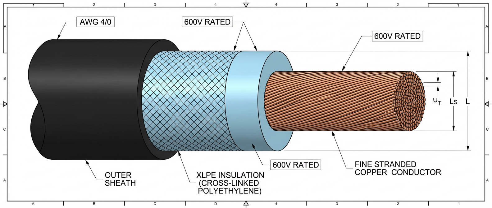
- Wiring and Protection: Use appropriately sized cables and fuses to minimize losses; include DC breakers and surge protectors for fault isolation.
- Commissioning: Calibrate MPPT and control settings; test under various conditions (e.g., partial shading) using tools like power analyzers.
- Monitoring and Optimization: Employ energy management systems (EMS) for real-time adjustments.
Real-world examples include Tesla’s Powerwall systems, which use DC coupling to integrate solar and batteries with a single inverter, achieving round-trip efficiencies of 90% or higher. Industry standards like IEC 62109 provide guidelines for safe implementation. (Sources: IEEE Paper on DC-coupled microgrids, 2020; and SMA Solar’s application notes.)
3. Technical Challenges
DC coupling introduces several technical challenges that stem from the need for precise voltage and power management across dynamic sources. These challenges impact efficiency, reliability, and cost:
- Voltage Matching and Stability: DC sources often have varying voltage outputs (e.g., PV voltage drops with shading, battery voltage fluctuates with state of charge). Maintaining a stable DC bus voltage requires advanced converters with wide input ranges, which can increase complexity and losses. For instance, mismatched voltages can lead to circulating currents or inefficiencies, reducing system efficiency by 2-5% if not managed properly. (Source: Research in IEEE Transactions on Industrial Electronics, 2021.)
- Efficiency Optimization: While DC coupling reduces conversion stages (e.g., from two or more in AC coupling to one or two in DC), each DC-DC converter adds its own losses (typically 1-3% per stage). High-frequency switching in converters can cause electromagnetic interference (EMI), requiring robust filtering. Techniques like synchronous rectification and soft-switching are used to mitigate this, but they demand sophisticated control.
- Control Complexity: Coordinating multiple sources—especially with bidirectional power flow for batteries—requires intelligent algorithms. This includes handling rapid transients (e.g., sudden cloud cover causing PV output drops) and ensuring seamless transitions between charging/discharging modes. Without fast response times (e.g., <10 ms), the system risks instability or shutdown.
- Safety and Protection: DC faults (e.g., arcs or short circuits) are harder to interrupt than AC faults due to the absence of natural zero-crossing points. This necessitates high-speed DC breakers and arc-fault detection devices (AFDDs), adding cost and design constraints. Standards like UL 1741 specify requirements, but implementation can be challenging.
- Thermal Management: Concentrated power flow on the DC bus increases heat generation, requiring effective cooling solutions (e.g., heat sinks or forced air) to prevent component degradation.
Overall, these challenges can elevate system costs by 10-20% compared to simpler AC-coupled designs, but they are offset by long-term energy savings. (Source: NREL cost-benefit analyses.)
4. Key Difficulties
The difficulties in DC coupling implementation are multifaceted, often arising from practical integration and operational hurdles:
- System Integration Issues: Ensuring compatibility between components (e.g., different battery chemistries like lithium-ion vs. lead-acid) can lead to interoperability problems. For example, batteries may require specific voltage windows that don’t align with PV output, necessitating custom converter designs. This increases development time and risk.
- Dynamic Response Management: Handling real-time variations, such as rapid PV output changes due to weather, demands high-speed controllers. Delays in response can cause voltage sags or overshoots, potentially damaging equipment. Simulations show that without adaptive MPPT, energy losses can exceed 10% in variable conditions.
- Cost and Scalability: While DC coupling is cost-effective for small-scale systems, scaling to utility levels (e.g., >1 MW) introduces difficulties with component availability and balance-of-system costs. High-voltage DC buses (e.g., 1500V) reduce losses but require expensive insulation and safety measures.
- Standardization Gaps: Despite standards like IEC 62109-2 for safety, there’s inconsistency in regional codes (e.g., NEC in the US vs. CE in Europe), complicating global deployments. Additionally, evolving technologies like gallium nitride (GaN) semiconductors offer efficiency gains but lack long-term reliability data.
- Fault Diagnostics and Maintenance: DC systems are prone to subtle faults (e.g., ground faults) that are harder to detect than in AC systems. This requires advanced monitoring tools, increasing operational complexity.
These difficulties underscore why DC-coupled systems often involve iterative prototyping and testing. Case studies from projects like the Hornsdale Power Reserve in Australia highlight how initial integration challenges can delay deployments. (Source: Industry reports from Wood Mackenzie.)
5. Important Considerations
When designing and operating a DC-coupled PCS, several critical factors must be addressed to ensure safety, performance, and longevity:
- Design Considerations:
- Component Selection: Use high-efficiency, wide-bandgap semiconductors (e.g., SiC or GaN) for converters to minimize losses. Ensure all devices are rated for the maximum system voltage and current.
- Voltage and Current Ratings: Size the DC bus to handle peak loads (e.g., 1.2x nominal rating for headroom) and include redundancy for critical components.
- Thermal Design: Incorporate adequate cooling, such as liquid cooling for high-power systems, to prevent overheating and extend lifespan.
- Safety Features: Implement multiple protection layers, including DC fuses, circuit breakers, and isolation monitoring, to comply with standards like UL 1741 and IEC 62109. Arc-fault detection is essential for fire prevention.
- Control Strategy: Develop robust algorithms using model predictive control (MPC) to handle source variability; include fail-safes for grid disconnections.
- Operational Considerations:
- Monitoring and Maintenance: Regularly inspect connections for corrosion or loosening; use remote monitoring systems to track performance metrics like efficiency and state of health. Schedule annual checks for capacitor degradation.
- Grid Interaction: For grid-tied systems, ensure anti-islanding protection to prevent backfeeding during outages, as per IEEE 1547 standards.
- Environmental Factors: Account for temperature extremes, which affect component efficiency (e.g., derating converters in hot climates).
- User Training: Educate operators on emergency procedures, such as manual shutdowns during faults.
- Residual Uncertainties and Risks:
- Long-Term Reliability: While DC coupling shows promise, data on 20-year durability is limited, especially with new materials. For example, GaN devices may degrade faster under high stress.
- Technological Evolution: Emerging innovations like AI-driven controls could simplify implementation but introduce integration risks. Uncertainty remains about cost reductions from mass production.
- Regulatory Changes: Standards for DC systems are evolving, potentially requiring retrofits; for instance, future updates to NEC Article 690 may impose stricter isolation requirements.
- Economic Viability: In regions with low electricity prices, the higher upfront cost of DC-coupled systems may not justify efficiency gains, depending on payback periods.
Proactive measures, such as pilot testing and lifecycle analysis, can mitigate these uncertainties. (Source: IEA PVPS Task reports.)

Conclusions and Key Insights
DC coupling in PCS represents a significant advancement for energy-efficient renewable integration, offering up to 15% higher efficiency than AC-coupled systems by minimizing conversion losses. Key insights include its suitability for hybrid PV-battery applications, where direct charging enhances round-trip efficiency to 90% or more. Implementation requires careful attention to voltage matching, control algorithms, and safety, with technical difficulties centered on dynamic response and cost scalability. However, challenges like fault protection and standardization gaps persist, necessitating ongoing innovation.
Important conclusions are:
- Positive Impacts: DC coupling reduces operational costs and carbon footprint over time, making it a cornerstone for sustainable energy systems.
- Residual Uncertainties: Long-term reliability of high-voltage components and regulatory alignment remain unresolved; further research is needed on degradation models and grid compatibility.
- Recommendations: Prioritize modular designs for flexibility, invest in advanced monitoring, and stay updated on standards. For widespread adoption, collaboration between manufacturers, utilities, and policymakers is crucial.
In summary, while DC coupling is a transformative technology with clear benefits, its success hinges on addressing implementation hurdles and uncertainties through continuous R&D and real-world validation. (Sources: Consolidated insights from academic journals and industry best practices.)



Add comment